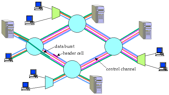
Figure 1: Burst Switching Concept
Abstract
Demand for network bandwidth is growing at unprecedented rates, placing growing demands on switching and transmission technologies. Wavelength division multiplexing will soon make it possible to combine hundreds of gigabit channels on a single fiber. These trends are leading to a growing mismatch between demand and WDM link capacity on the one hand, and the speed of electronic switching and routing, on the other hand. This paper presents a technique called burst switching, which is designed to facilitate greater use of optical technology in the data paths of future switches and routers. Burst switching separates burst level data and control, allowing major simplifications in the data path. To handle short data bursts efficiently, the burst level control mechanisms in burst switching systems must keep track of future resource availability when assigning arriving data bursts to channels or storage locations. The resulting lookahead resource management problems raise new issues and require the invention of completely new types of high speed control mechanisms.Table of Contents
Introduction
Network Architecture
Key Performance Issues
Scalable Burst Switch Architecture
Lookahead Resource Management
Closing Remarks
Burst switching systems assign user data bursts to channels in WDM links on-the-fly in order to provide efficient statistical multiplexing of high rate data channels and are designed to make best use of optical and electronic technologies. The transmission links in a burst network carry multiple WDM channels, which can be dynamically assigned to user data bursts. One channel is reserved for control information. The information in the control channel is interpreted by the control portion of the switching systems, while the data channels are switched through transparently with no examination or interpretation of the data. This separation of control and data simplifies the data path implementation, facilitating greater use of optical switching technologies within the data path. At the same time, electronics is used to implement the control portion of the system, providing the sophisticated routing and resource management mechanisms required for Internet routers.
This paper presents a scalable burst switch architecture that can be used to construct systems with aggregate capacities exceeding 100 Tb/s. The system routes data bursts using IPv4 or IPv6 addresses and directly supports multicast, as well as unicast burst transmission. The key mechanisms required to support look-ahead resource management are described in some detail. These include look-ahead channel allocation algorithms and algorithms to allocate memory for storing bursts temporarily during congestion periods. These resource allocation algorithm use a differential search tree to project future buffer usage and allows the hardware scheduling mechanisms to quickly determine if an arriving burst can be accommodated, and to incrementally update the scheduling information to reflect the arrival and departure of each burst.

Figure 1: Burst Switching Concept
The format of data sent on the data channels is not constrained by the burst switching systems. Data bursts may be IP packets, a stream of ATM cells, frame relay packets or raw bit streams from remote data sensors. However, since the burst switching system must be able to interpret the information on the control channel, a standard format is required there. In this paper, ATM cells are assumed for the control channel. While other choices are possible, the use of ATM cells makes it possible to use existing ATM switch components within the control subsystem of the burst switch, reducing the number of unique components required.
When an end system has a burst of data to send, an idle channel on the access link is selected, and the data burst is sent on that idle channel. Shortly before the burst transmission begins, a Burst Header Cell (BHC) is sent on the control channel, specifying the channel on which the burst is being transmitted and the destination of the burst. A burst switch, on receiving the BHC, selects an outgoing link leading toward the desired destination with an idle channel available, and then establishes a path between the specified channel on the access link and the channel selected to carry the burst. It also forwards the BHC on the control channel of the selected link, after modifying the cell to specify the channel on which the burst is being forwarded. This process is repeated at every switch along the path to the destination. The BHC also includes a length field specifying the amount of data in the burst. This is used to release the path at the end of the burst. If, when a burst arrives, there is no channel available to accommodate the burst, the burst can be stored in a buffer.
BHCs include the IP address of the destination terminal, and each switch selects an outgoing link dynamically from among the set of links to that destination address. This requires that the switch consult a routing database at the start of each burst, to enable it to make the appropriate routing decisions. To handle 2.4 Gb/s channels, this requires the ability to perform an IP lookup roughly every 160 ns. Fortunately, new hardware-based IP lookup algorithms can achieve this processing rate and expected improvements should yield lookup times of under 50 ns in a few years.
Consider a multiplexor that assigns arriving bursts to channels in a link with h available data channels and storage locations for b bursts. An arriving burst is diverted to a storage location if when it arrives, all h data channels are in use. A burst will be discarded if it arrives when all h channels are busy and all b burst storage locations are being used by bursts that have not yet been assigned a channel. However, once a stored burst has been assigned to an output channel, its storage location becomes available for use by an arriving burst, since the stored burst will vacate space at the same rate that the arriving burst occupies it.
The multiplexor can be modeled by a birth-death process with b+h+1 states, where the state index i corresponds to the number channels in use plus the number of stored bursts that are waiting to be assigned a channel. The transition rate from state i to state i+1 is equal to the burst arrival rate for all i less than b+h. The transition rate from state i to state i-1 is min{i,h} times the channel data rate divided by the burst length. Using standard methods, we can solve the for steady-state probabilities. The burst discard probability is then just the steady-state probability for state b+h.
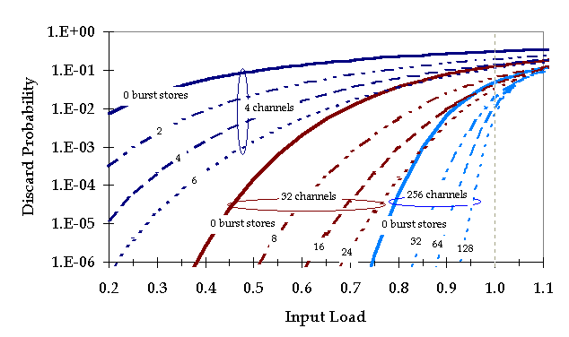
Figure 2: Burst Discard Probability
Figure 2 shows the burst discard probability for links with 4, 32 and 256 channels, with several different choices for the number of burst stores. Note that when the number of channels is large, reasonably good statistical multiplexing performance can be obtained with no burst storage at all. With 32 channels, 8 burst stores is sufficient to handle bursty data traffic at a 50% load level (an average of 16 of the 32 channels are busy), with discard probabilities of less than one in a million. With 256 channels and 128 burst stores, loading levels of over 90% are possible with low loss rates.
The second key performance issue for burst switches is the overhead created by timing uncertainty. When a user terminal has a burst to send, it first sends a BHC on the control channel of its access link and shortly afterwards, it sends the burst. The BHC includes an offset field that specifies the time between the transmission of the first bit of the BHC and the first bit of the burst. When BHCs are processed in burst switches, they are subject to variable processing delays, due to contention within the control subsystem of the burst switch. To compensate for the delays experienced by control cells, the data bursts must also be delayed. A fixed delay can be inserted into the data path by simply routing the incoming data channels through an extra length of fiber. To maintain a precise timing relationship between control and data, BHCs are time-stamped on reception. When a switch is preparing to forward a BHC on the output link, it compares the time stamp to the current time, in order to determine how much delay the BHC has been subjected to in its passage through the burst switch. Knowing the (fixed) delay of the data path, it can then recalculate the offset between the BHC and the data. It can also impose some additional delay on the BHC if necessary, to keep the offset from becoming excessively large. If the burst was buffered in the burst switch, the queueing delay must also be taken into account, when recomputing the offset.
As a burst progresses through a burst network, there is some inevitable loss of precision in the offset information. Timing uncertainty arises from two principal sources. First, signals using different wavelengths of a WDM link travel at different speeds down the fiber. While the absolute magnitudes of these differences are not large (under 1 microsecond for links of 1000 km), they are significant enough to be of concern. Fortunately, they can be compensated at the receiving end of a link, if the approximate length of the fiber is known. Given the length information, the difference in the delay between the control channel and each of the data channels can be calculated and the receiving control circuitry can adjust the offset associated with an arriving burst, accordingly. Note, that this does not require inserting optical delays in the data channels. The control subsystem, simply adjusts the offset value in the BHC to reflect the differences in delay across channels. While this compensation is not perfect, it can be made accurate enough to keep timing uncertainties due to this cause under 100 ns on an end-to-end basis in a wide area network.
Another source of timing uncertainty is clock synchronization at burst switches along the path in a network. When data is received on the control channel at a burst switch, the arriving bit stream must be synchronized to the local timing reference. There is some inherent timing uncertainty in this synchronization process, but the magnitude of the uncertainty can be reduced to very small values using synchronizers with closely-spaced taps. Even with fairly simple synchronizer designs, it can be limited to well under 10 ns per switch. In an end-to-end connection with ten switches, this results in an end-to-end timing uncertainty of 100 ns.
Within switches, it's possible to avoid significant loss of timing precision, since all control operations within a switch can be synchronized to a common clock, and since the data path delays in a switch are fixed and can be determined with high precision. Thus, the end-to-end timing uncertainty is essentially the sum of the uncertainty due to uncompensated channel-to-channel delay variation on links and the uncertainty due to synchronization. If the end-to-end uncertainty is limited to 200 ns then bursts with durations of 2 microseconds can be handled efficiently. This corresponds to 600 bytes at 2.4 Gb/s.
It's possible to avoid the necessity for tight end-to-end timing control if the switches interpret the information sent on the data channels so that they can explicitly identify the first and last bit of a burst. While this is reasonable to do in electronic implementations, it is more difficult in systems with optical data paths. In addition, it constrains the format of data that can be sent on the data paths, at least to some degree.
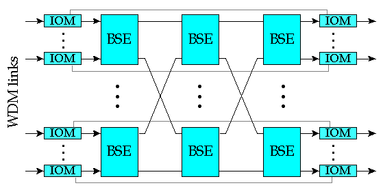
Figure 3: Scalable Burst Switch Architecture
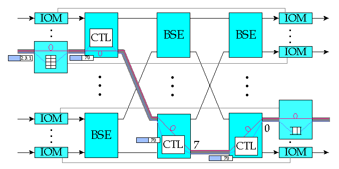
Figure 4: Burst Switch Operation
The operation of the burst switch is illustrated in Figure 4. An arriving burst is preceded by a Burst Header Cell (BHC) carried on one of the input channels dedicated to control information. The BHC carries address information that the switch uses to determine how the burst should be routed through the network, and specifies the channel carrying the arriving data burst. The IOM uses the address information to do a routing table lookup. The result of this lookup includes the number of the output port that the burst is to be forwarded to. This information is inserted into the BHC, which is then forwarded to the first stage BSE. The data channels pass directly through the IOMs but are delayed at the input by a fixed interval to allow time for the control operations to be performed.
When a BHC is passed to a BSE, the control section of the BSE uses the output port number in the BHC to determine which of its output links to use when forwarding the burst. If the required output link has an idle channel available, the burst is switched directly through to that output link. If no channel is available, the burst can be stored within a shared Burst Storage Unit (BSU) within the BSE. In the first stage of a three stage network, bursts can be routed to any one of a BSE's output ports. The port selection is done dynamically on a burst-by-burst basis to balance the traffic load throughout the interconnection network. The use of dynamic routing yields optimal scaling characteristics, making it possible to build large systems in which the cost per port does not increase rapidly with the number of ports in the system. At the output port of a burst switch, the BHC is forwarded on the outgoing link and the offset field is adjusted to equal the time delay between the transmission of the first bit of the BHC and the first bit of the burst.
The total bandwidth consumed by multicast traffic on the recycling ports is strictly less than the total bandwidth consumed on output links that are not recycling ports. If d is the fraction of the outgoing traffic that is multicast, then a system with m output links will need dm recycling ports. Since d is typically fairly small (say 0.1), the incremental cost of multicast is also small. In any case, the incremental cost of multicast switching is just a small constant factor over the cost of a comparable system that only supports unicast. All known single pass multicast methods, on the other hand, lead to a multiplicative cost increase that grows at least as fast as the logarithm of the number of ports. The multipass approach also makes it easy to add endpoints to or remove endpoints from a multicast, and can be used to provide scalable many-to-many multicast, as well as one-to-many. This method has been adapted from the ATM switch architecture described in [CHA97]; further details can be found there and in references [TUR94,TUR96].
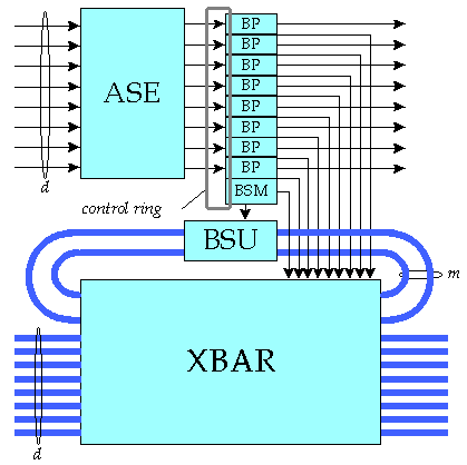
To enable effective control of dynamic routing, BSEs provide flow control information to their upstream neighbors in the interconnection network. This can take any of several forms. Since some BSE outputs may have channels available, even when other outputs are congested, it is most useful to supply flow control information that reports the status of different outputs. Each output that has sufficiently many spare channels can enable transmission of new bursts by the upstream neighbors, by sending the appropriate flow control indication to the upstream neighbors. This communication takes place in two steps. First, each BP in a BSE shares its flow control information with the other BPs in the same BSE (using the local control ring). Then each BP in the BSE sends its own flow control information and that of the other BPs to one of the BSE's upstream neighbors. This communication takes place using a set of upstream control signals not shown in the figure.
The simple horizon-based scheduling algorithm can waste resources since it only keeps track of a channel's last idle period. While it attempts to minimize the size of the gaps between successive bursts, its failure to maintain information about those gaps means that it cannot schedule short bursts within the gaps. In one important special case, horizon scheduling can produce optimal results. In particular, if the variation in the offsets between BHCs and bursts is smaller than the smallest burst length, then there is no opportunity to use the gaps between bursts in any case. In systems with no buffering, it's possible to make this condition hold. However, we will return to the issue of more general channel scheduling methods following consideration of buffer scheduling.

Figure 6: Burst Storage Scheduling
This can be done by extending a search tree data structure such as a 2-3 tree (2-3 trees are a special case of B-trees [COR90]). The right hand portion of Figure 6 shows a 2-3 tree that represents the buffer usage curve at the left. The leaves in this search tree contain pairs of numbers that define the left endpoints of the horizontal segments of the buffer usage curve. Each interior node of the search tree contains entries specifying the smallest time values appearing within the node's subtrees. These time values allow one to determine the range of times represented by a given subtree without explicitly examining all the nodes in the subtree. The basic search tree allows one to quickly determine the buffer usage at an arbitrary point, but does not provide all the capabilities required for efficient look-ahead buffer management. We need a representation that allows one to quickly determine the maximum buffer utilization from a starting time to an ending time, so that we can determine if there is space to store a burst from the time it arrives until the time it will be forwarded. In addition, should we decide to store a burst, we need to quickly modify the data structure to represent the addition of the new burst.
These capabilities can be implemented using a differential data representation. This is illustrated in Figure 7 which shows a search tree that represents the same buffer usage curve. In this search tree, each entry in a node consists of three values a time, a field called Dbuf and a field called Dmax. The time values are the same as in the original search tree and we can use the other two fields to quickly determine the maximum buffer utilization in an interval and to incrementally modify the data structure. The values of the Dbuf fields are chosen so that the sum of the values from the root to any leaf entry gives the buffer usage for the corresponding entry in the original, non-differential search tree. This is illustrated in Figure 7 by noting that the Dbuf values along the root to the leaf entry with time value 8, sum to 4. By consulting the original search tree and the buffer usage curve from which it was derived, we see that indeed, the buffer usage starting at time 8 is 4. In addition, if for any entry in any node one adds the Dmax value of that entry to the sum of the Dbuf values along the path from that entry to the root, one obtains the value of the maximum buffer utilization within the subtree below the given entry. By adding the Dmax value in the highlighted entry of the second level node on the left of Figure 7, to the Dbuf value in that entry and the one above it, at the root of the tree, we obtain 6. This is the maximum buffer utilization in the subtree below the highlighted entry in the second level node, as one can easily confirm by consulting Figure 6.
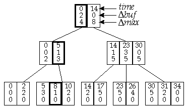
The differential representation allows one to rapidly determine the maximum buffer utilization within a time interval, allowing a Burst Storage Manager to decide if an incoming burst can be stored without exceeding the available storage space. It also allows rapid incremental updating. In general, we can perform any of the required operations in O(log n) time, where n is the number of stored bursts. To obtain the highest possible operating speed, we would like to reduce the number of levels in the search tree. This can be done using the well-known generalization of the 2-3 tree to a B-tree, in which each node has between B and 2B entries. A search tree capable of storing information for n/2 bursts requires a maximum of logB n levels. If the memory implementing the differential search tree is stored in the Burst Storage Manager's on-chip memory, one can accommodate nodes with B as large as 8 or 16, keeping the required search tree depth relatively small.
Looking ahead into the next decade, we can anticipate continuing improvements in both electronics and optical technology. In the case of electronics, there will be continuing dramatic improvements in circuit density and substantial but smaller improvements in circuit speed. Improvements in circuit speeds will be more limited because of the qualitative differences that arise when bit times become comparable to or smaller than the propagation times between circuit components. In this domain, the mechanisms for sending and receiving data reliably are far more complex than in lower speed systems.
In the optical domain, we can also expect to see substantial improvements. Optoelectronic transmitter and receiver arrays will become widely deployed in commercial applications and the technology to integrate semiconductor optical amplifiers along with passive waveguide structures should mature sufficiently to find application in a variety of systems. Growing demand for WDM transmission systems should stimulate development of components that are more highly integrated and more cost-effective. These trends in electronic and optical technology all appear to favor network technologies like burst switching. This suggests that such technologies could play an important role in the communication networks of the twenty-first century.
REFERENCES