|
CS/COE 535 |
Acceleration of Algorithms in Reconfigurable Hardware |
Lockwood, Fall 2003 |
|
Assigned |
Wednesday, September 24th, 2003 |
|
Due Date |
Friday, October 3rd, 2003 5 pm |
|
Purpose: |
Introduction to the FPX Environment and |
|
Points |
(100 points) |
In Homework 1 you analyzed the control packet processor, viewing how it traverses through an IP packet. In addition, you saw how it set the packet type to be either TCP or UDP. Now we are going to build upon the pre-existing state machine to deal with control packets as well as add a statistics application to this application.
Your goal in this assignment is to use the state machine from Homework 1, the statistics counter you built in Homework 2 and Homework 3 to count the number of TCP, UDP, Control, or generic IP packets that are input to the network application. By the end of this assignment you will have learned:
FPX Environment Basics
CAD Tool Usage (ModelSim, Synplicity, and Xilinx).
High level design
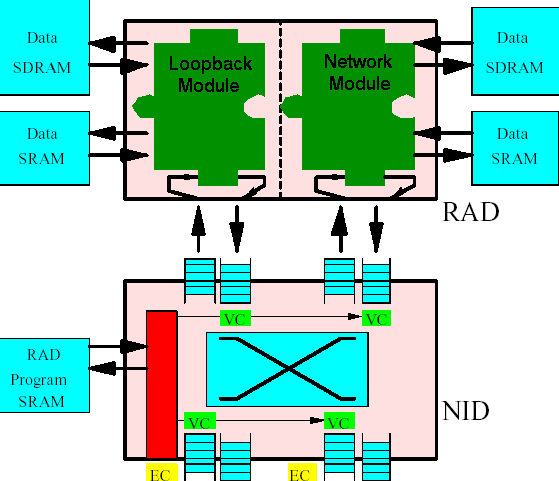
Our application will be implemented in the Reprogrammable Application Device (RAD), which currently is a Xilinx XCV2000E class FPGA. The RAD is configured as in Figure 1. Note that the loopback module sits on the switch interface (egress path), while our network application sits on the line card interface (ingress path).

Figure 1: RAD Configuration.
The loopback module simply feeds incoming traffic back out on the outgoing traffic port. The network module is where we will implement our design, as shown in Figure 2.

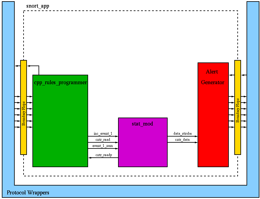
Figure 2: Network module block diagram.
In this mp, we will be modifying the contents of snort_app.vhd. This file, sits inside the Protocol Wrappers, as Figure 2 shows. For this Machine Problem, we need only consider the signals of the IP wrapper interface (later, we will also consider SRAM and SDRAM signals). A list of the input and output signals can be found in Table 1.
|
Input Side |
Output Side |
|
|
The alert_generator.vhd component has been provided for you. It is responsible for forming an UDP alert packet to be sent to a designated location. This will allow you to send in a control packet to read a counter number from your statistics module.
Note that space has been left in the diagram of Figure 2. We will be adding additional components to this as the semester progresses.
Directions:
Part 0: Download the MP1 Distrubution file here. The following files are of note.
snort_app.vhd - top level entity to be used in this class
cntr_ram.vhd - representation of a Block RAM with 256 16-bit entries
cpp_rules_programmer.vhd - finite state machine that you analyzed in Homework #1
alert_generator.vhd - component which creates UDP alert packets
testbench.vhd - component to be used for simulation that mimics IP wrapper interface
clock.vhd - component that instantiates a clock
makefile - script file to compile, simulate, and synthesize your design
mp1_wave.do - wave list to be used for turned in simulation
mp1_test.dat - input data cell to be used for testing
Part 1: Modifying the CPP to interface with stat_mod and process control packets
Control Packets are essential to the operation of this
application. They allow for changes to be made and status to
be read. Our control packets are UDP packets sent to a
specific port (x"BEEF" in this case). This specific port
was chosen just because it is easier to see in simulation. Refer to
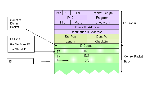
Figure 3 for the control packet format we will use in this
assignment. The format consists of an opcode being placed in the first word (bits 31 downto 24) and an event number to read placed in the second word (bits 31 downto 16). So, if we want to read the number of tcp packets our module has seen, we will place x"0001" in the stat to read field.
The reason the stat to read field is 16 bits is that we may instantiate
multiple counters later and select which one to read based on the upper
bits. For now, when you receive a control packet to read a
counter, you only need to look at bits 23 downto 16 of the stat to read
word.

Figure 3: Control Packet Format.
In this machine problem, we will implement opcode x"84" (or decimal 132) to read a specified counter number from your statistics component.
Modify the CPP to:
The generation of the response message is provided for you in alert_generator.vhd. You will not need to modify this file. You will simply have to hook the data strobe and cntr_data signals to the alert_generator component.
In order to count packet type, let's define the following event numbers:
Event Number 0 = IP Packet that is not TCP, UDP, or Control
Event Number 1 = TCP Packet
Event Number 2 = UDP Packet (Do NOT count control packets in this group)
Event Number XX = Use the 8-bit Opcode as the event number to count a control packet
Modify your state machine to assign the outputs inc_event_1, cntr_read, and event_1_num. (Hint: You will need to modify the entity declaration and the outputs process description).
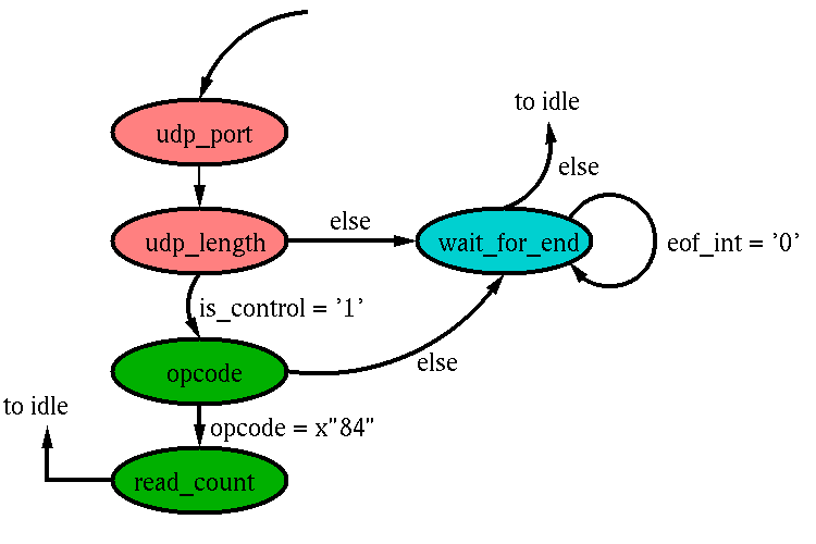
A suggested modification to the state machine is shown below in Figure 4.

Figure 4: A suggested form for changing the cpp to handle control packets.
Part 2: Modifying Top Level to include your components.
Now that you have a CPP that can count packet type and recognize control packets, modify the top level entity, snort_app.vhd, to reflect these changes.
Add signals to the entity declaration of cpp_rules_programmer.vhd
Add signals that run between components
Add your stat_mod component.
Wire up the stat_mod to both the cpp and alert generator.
In addition, you must tie up the signal 'tca_out_appl_int'. This signal is used as a back pressure indicator to senders. When this signal is low ('0'), that means that this module cannot accept any incoming packets. When it is high ('1'), it can accept incoming packets. The only time that our module cannot accept packets is when our statistics counter is resetting memory. Use your cntr_ready signal to assign the output of tca_out_appl_int.
Part 3: Simulation
Now that you have wired up your statistics module into the top level snort_app.vhd, you can proceed to simulate your design in ModelSim.
Using this waveform list, simulate the testbench. Make sure you have this mp1_test.dat file in your sim directory. You will have to rename it to input_IP.dat.
You are encouraged to use your program from HW 2 to generate your own test traffic to test your circuit.
Part 5: Synthesis and Build
Use Synplicity to make an edn file for your design. Follow this tutorial for a how to use the Synplicity software for our application.
Once you have completed synthesis, use the provided makefile in the backend directory. From a cygwin shell, type 'make build'.
This will generate a bitfile if there are no errors. You will submit this bitfile to the online test server to test it in hardware.
Table 2: Symbol Key
|
|
|
|
|
Of Interest |
Modify |
Synthesizable |
Table 3: Contents of MP1.tar.gz
|
|
MP1/sim/ Simulation Folder |
|
|
||||
|
|
|
makefile |
Example make file used to automate compilation and simulation. |
|
|
|
|
|
|
|
mp1_wave.do |
Wave list including top level of snort_app.vhd and cpp_rules_programmer.vhd |
|
|
|
|
|
|
|
mp1_test.dat |
Test data packets. |
|
|
|
|
|
|
|
||||||
|
|
MP1/backend/ Backend Folder |
||||||
|
|
|
bitgen.ut |
Bitfile generation constraints file. |
|
|
|
|
|
|
|
cellproc.edn |
Cell Processor EDN specification. |
|
|
|
|
|
|
|
cntr_ram.edn |
16 by 256 Block RAM EDN specification. |
|
|
|
|
|
|
|
fifo15x35.edn |
Wrapper Specific FIFO. |
|
|
|
|
|
|
|
fifo31x32.edn |
Wrapper Specific FIFO. |
|
|
|
|
|
|
|
fifo32x36.edn |
Wrapper Specific FIFO. |
|
|
|
|
|
|
|
fifo_127x32.edn |
Wrapper Specific FIFO. |
|
|
|
|
|
|
|
fifo_15x32.edn |
Wrapper Specific FIFO. |
|
|
|
|
|
|
|
fifo_15x7.edn |
Wrapper Specific FIFO. |
|
|
|
|
|
|
|
fifo_16_by_16.edn |
Alert Generator Specific FIFO. |
|
|
|
|
|
|
|
fifo_16_by_32.edn |
Alert Generator Specific FIFO. |
|
|
|
|
|
|
|
fifo_512x32.edn |
Wrapper Specific FIFO. |
|
|
|
|
|
|
|
fifo_512x34.edn |
Wrapper Specific FIFO. |
|
|
|
|
|
|
|
frameproc.edn |
Frame Processor EDN specification. |
|
|
|
|
|
|
|
ipproc.edn |
IP Processor EDN specification. |
|
|
|
|
|
|
|
llc_proc.edn |
LLC EDN specification. |
|
|
|
|
|
|
|
makefile |
File used to build your design. |
|
|
|
|
|
|
|
network_application_core.edf |
Top level EDF file, generated by synplicity. |
|
|
|
|
|
|
|
network_application_core.pcf |
Constraints file generated by Synplicity. |
|
|
|
|
|
|
|
rad.ucf |
Pin constraints file. |
|
|
|
|
|
|
|
ram512x16.edn |
Wrapper Specific Block RAM. |
|
|
|
|
|
|
MP1/syn/ Synthesis Source Folder |
||||||
|
|
|
Nothing yet, but you will add a snort_app.prj file. |
|||||
|
|
MP1/vhdl/ VHDL Source Folder |
||||||
|
|
|
testbench |
|||||
|
|
|
|
clock.vhd |
The vhdl file for simulating the Cell Processor. |
|
|
|
|
|
|
|
IP_packets_in.vhd |
The vhdl file for simulating interface from our network application into the IP Wrapper. |
|
|
|
|
|
|
|
IP_packets_out.vhd |
The vhdl file for simulating interface from the IP Wrapper into our network application. |
|
|
|
|
|
|
|
testbench.vhd |
The main simulation file. You will simulate this entity. |
|
|
|
|
|
|
alert_generator.vhd |
UDP Alert message generator |
|
|
|
|
|
|
|
alert_generator_fsm.vhd |
Packet generator control FSM |
|
|
|
|
|
|
|
cpp_rules_programmer.vhd |
Main FSM. |
|
|
|
|
|
|
|
cntr_ram.vhd |
Block RAM component |
|
|
|
|
|
|
|
fifo_16_by_32.vhd |
Fifo Used by the alert generator |
|
|
|
|
|
|
|
snort_app.vhd |
Top Level Design Unit |
|
|
|
|
Things to Turn In:
Here is a checklist of the things you need to turn in:
Part 0: Download of Distribution File
Nothing to Submit
Part 1: Modification of CPP
Modified cpp_rules_programmer.vhd file. ( 5 pts)
Modified state machine bubble diagram showing all transition cases and assignments. ( 5 pts)
Part 2: Modification of Top Level
Modified snort_app.vhd file. ( 5 pts)
Part 3: Simulation
Simulation waveforms using specified waveform list and mp1_test.dat. ( 10 pts)
Part 4: Synthesis and Build
Submit the requested waveforms and the 'snort_app.vhd' to the Electronic Homework Server. ( 25 pts)
Submit synthesized .bit file to the test server where it will be tested in hardware. ( 75 pts)
Follow the instructions on the server, it will inform you if your design passed or not.